ReliabiliTTy® 2.0 technology from SafeTTy Systems

At SafeTTy Systems, we help our customers to develop software for reliable space-based systems, automotive systems (including autonomous vehicles), industrial control systems, medical systems, railway systems, sports equipment …
We do this by developing and applying ReliabiliTTy® software frameworks that are designed to make it much easier to provide clear evidence that systems will meet ‘safety goals’ and comply with both local regulatory requirements and international safety standards.
ReliabiliTTy frameworks are based on state-of-the-art “Time-Triggered” (TT) software architectures that incorporate patented monitoring capabilities.
This page provides a guide to TT software architectures and ReliabiliTTy technology:
- we present our views on the differences between use of a ‘TT System’ and the use of a conventional ‘Real-Time Operating System‘ (RTOS);
- we explore the extensive self-monitoring capabilities that are provided by ReliabiliTTy 2.0 software platforms;
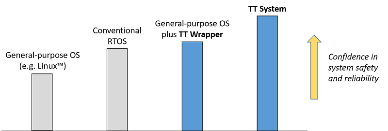
- we explain how ‘TT Wrappers‘ can improve the safety and reliability of designs that employ a general-purpose operating systems (such as Linux™);
- we provide links to a suite of public TT design examples and to our popular ‘ERES2‘ book.
Note:
- You may find it useful to refer to our ‘Foundations of TT embedded systems‘ guide before reading this page.
- You may find it useful to refer to our list of Definitions while reading this page.
- You may also like to review our examples of recent customer projects.
[This page was last updated: 2024-01-03]![]()
![]()
Our focus
![]()
We help our customers to develop software for reliable space-based systems, automotive systems (including autonomous vehicles), industrial control systems, medical systems, railway systems, sports equipment …
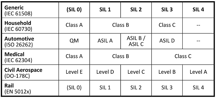
Where required, we help our customers to achieve compliance with one or more international safety standards: ISO 26262, IEC 61508, ISO 13849, IEC 62304, IEC 60730 …
We support ‘fail safe’ and ‘fail operational’ designs.
![]()
![]()
![]()
An overview of our approach
![]()
- We specialise in the engineering of very simple software designs for high-reliability / safety-related / safety-critical embedded systems.
- Keeping the designs simple allows us to model them precisely (at design time) and monitor them closely (at run time).
- Our modelling and monitoring process allows us to provide clear evidence that the systems we support will meet their safety requirements (and the requirements of international safety standards).
Many of our customers apply our technology to build a complete ‘TT System‘.
In other cases, our customers use our technology to build a ‘TT Wrapper‘: this is a monitoring unit that is used to improve confidence in the safe operation of a (pre-existing) complex component or system.
(We say more about TT Systems and TT Wrappers in the sections below.)
To summarise: when comparing systems based ‘Real-Time Operating Systems’, conventional operating systems (such as Linux) and TT alternatives, our experience is that the world looks something like this:
![]()
![]()
ReliabiliTTy 2.0 vs. RTOS
Two software architectures are used in embedded systems: these can be labelled as ‘event triggered’ (ET) and ‘time triggered’ (TT). The key differences between ET and TT systems arises from the way that the tasks are released.
For many developers, ET architectures are more familiar. A typical ET design will be required to handle multiple interrupts. For example, interrupts may arise from periodic timer overflows, the arrival of messages on a CAN bus, the pressing of a switch, the completion of an analogue-to-digital conversion and so on. In an ET system, the development team is likely to write an ‘interrupt service routine’ (ISR) to deal with each of these interrupts.
In larger designs, these ISRs may be integrated into a conventional ‘Real-Time Operating System‘ (RTOS) platform. The development team then needs to demonstrate that ISR releases (which may occur at ‘random’ points in time) and the RTOS task releases (which may occur in various combinations) can always be handled correctly.
The key advantages of RTOS / ET designs are that [i] the architecture is familiar to many developers; [ii] it is easy to build a prototype. On the other hand, a key challenge with such designs is that there may be a very large number of possible system states: this can make it very difficult to provide clear evidence that the resulting system will always operate correctly. This, in turn, means that long test cycles (sometimes very long) can be required in order to provide evidence of compliance with safety requirements and international safety standards.
The alternative to an ET / RTOS architecture is a time-triggered (‘TT’) architecture. When saying that an embedded system has a TT architecture we mean that it executes at least one set of tasks according to a predetermined schedule. The schedule determines the order of the tasks releases, the time at which each task is released, and whether one task can interrupt (pre-empt) another task.
In most cases, the starting point for the implementation of a TT design is a simple task scheduler: that is, the system will not usually employ a conventional RTOS, Linux™ or Windows®. In this software framework, a single interrupt will be used, linked to the periodic overflow of a timer. A ‘polling’ process will then allow interaction with peripherals.
The deterministic behaviour of such simple TT designs means that – compared with an equivalent RTOS-based design – it is easy to provide evidence that the system will operate in compliance with its safety requirements (and international safety standards) at all times.
We are sometimes asked by developers who are used to working with a conventional RTOS what the fundamental difference is between the design a TT system and design of an equivalent RTOS-based system.
The starting point for the two approaches is the same: both TT designs and RTOS designs are based on sets of periodic tasks.
From this common foundation, the two approaches diverge:
- in the case of TT designs, tasks are usually co-operative (non-pre-emptive) in nature, and – in normal operation – the only active interrupt will be the periodic timer tick;
- in the case of an RTOS-based design, task pre-emption is almost always employed, and additional (asynchronous) interrupts are usually enabled – for example, to deal with CAN messages that may arrive at ‘random’ times.
These differences may appear small, but they have a significant impact on our ability to model the system behaviour.
One way of thinking about this is to consider ‘MISRA® C’.
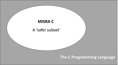
For developers of many general-purpose embedded systems, the C programming language is a common choice. For developers of safety-related embedded systems, use of ‘standard C’ is unusual. Instead, a subset of the language – such as the ‘MISRA C’ subset – is much more likely to be employed. Such language subsets are intended to improve system reliability and safety by avoiding use of features (the ‘goto’ statement is a simple example) that are known to be problematic in some designs.
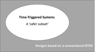
In our view the relationship between TT designs and designs based on a conventional RTOS can be viewed in a similar way (at the level of software architecture rather than programming language). In other words:
TT designs can be viewed as a ‘safer subset’ of a more general class of ET / RTOS designs. TT designs have much in common with ET / RTOS designs, not least the use of periodic task sets, but they minimise (or avoid completely) the use of features – such as task pre-emption and asynchronous interrupts – that are known to make system behaviour less deterministic.
![]()
A closer look at the (self) monitoring capabilities provided by ReliabiliTTy 2.0 platforms
When compared with conventional computer systems, designs based on ReliabiliTTy 2.0 have extensive self-monitoring capabilities: these capabilities allow us to be confident that the system will detect faults during system operation, typically within a period of 100 ms. This represents a key technical benefit for developers of many types of system. We explain more about the self-monitoring capabilities of systems based on ReliabiliTTy 2.0 platforms in this section.
In most conventional computer systems, ‘Power On Self Tests’ (POSTs) and periodic ‘Built-In Self Tests’ (BISTs) are (as the name suggests) ‘self tests’. The self-test nature of POSTs and BISTs raises two key challenges: [i] if the processor that is performing these tests is not operating correctly, a failed test may report that it has completed successfully, or the result of a failed test may be interpreted incorrectly; [ii] if failure of a POST or BIST is interpreted correctly, then the (faulty) processor may not be able to enter a Fail-Safe State (or implement any other form of shut down or fault-recovery behaviour that may be required).
Most ReliabiliTTy 2.0 platform configurations employ a separate core or processor within the platform to [i] assess the results of POSTs and BISTs; and [ii] move the processor that is being tested into a fail-safe state if a particular test is determined to have failed; this ‘independent assessment’ provides greater confidence that the results of POSTs and BISTs will be interpreted and handled correctly.
In addition to the self-test nature of conventional POSTs and BISTs, two further issues need to be considered when perform self tests on an embedded system: [i] the nature of the tests to be performed (including the level of diagnostic coverage required); and [ii] the interval over which the BISTs need to be performed.
Turning first to the nature of the tests that need to be performed, the deterministic nature of TT software architectures makes it comparatively easy to model the operation of real-time computer systems that are based on such a platform. This is a reason that TT designs are often used in safety-critical systems, high-integrity systems and in other products where system safety and/or reliability are important design considerations.
Processes for modelling TT designs are discussed in detail in the ERES2 book. Such models are necessarily based on various assumptions, including the following:
- the processors in the system operate correctly;
- the peripherals on each processor operate correctly;
- the processors are loaded with the correct software;
- the schedulers on each processor operate correctly;
- data can be transferred between tasks on the same processor without corruption;
- data can be transferred between processors without corruption;
- the tasks on each processor operate in compliance with their pre-determined ‘Best Case Execution Time’ (BCET) and ‘Worst Case Execution Time’ (WCET) limits; and
- the tasks on each processor in each operating mode are released in compliance with the pre-determined task sequence for this mode.
If any of these assumptions become invalid during the system operation, the system may not behave as expected in the field.
Some of the potential hazards and threats that may need to be considered are as follows:
- hardware failures that may result (for example) from electromagnetic interference, or from physical damage;
- residual software ‘bugs’ that may remain in the system even after test and verification processes are complete; and
- deliberate software change that may be introduced into the system, by means of ‘computer viruses’ and similar security-related attacks.
Many existing TT designs incorporate run-time monitoring that is intended to ensure that the assumptions summarised above remain valid while the system is operating, even in the presence of such hazards and threats. This process is discussed in the ERES2 book.

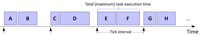
As an example of the kind of monitoring that is performed in conventional TT designs, an internal MoniTTor mechanism is employed in most systems. One purpose of the MoniTTor is to check that, during normal operation of a system, none of the tasks in the system takes longer to execute than their pre-determined ‘Worst-Case Execution Time’ (WCET). The MoniTTor is a key safety mechanism in many computer systems because failure of a task to complete its operation within the WCET limit may indicate a significant underlying problem with the system. If, in normal operation, the MoniTTor detects that a task has exceeded its pre-determined WCET, it is usually expected that the MoniTTor will attempt to move the system into a Fail-Safe State.
During normal system operation, the MoniTTor will be employed every time a task is released in order to check that the task does not exceed its pre-determined WCET limit.
The MoniTTor itself also needs to be tested, usually by means of POSTs and BISTs. As part of these tests, a fault that will force a task to have an execution time greater than its pre-determined WCET may be injected. A consequence of this is that a full test of the MoniTTor may result in the system entering a Fail-Safe State. A processor reset may then be required to return the processor to a normal operating mode.
To summarise. During normal operation of a TT computer system, monitoring mechanisms such as the MoniTTor need to be: [i] used (that is, monitoring needs to be performed); and [ii] tested (for example, the MoniTTor needs to be the subject of POSTs and BISTs, otherwise there cannot be confidence that the monitoring process performed by this mechanism will be carried out correctly).
POSTs and BISTs will clearly take time to complete and if not handled with care performing such tests may disrupt the normal system operation.
For most TT designs, performing tests of mechanisms such as the MoniTTor during POSTs is usually comparatively straightforward because the system will not be performing safety-related activities immediately after it is powered on. It is therefore usually acceptable to take a little time (perhaps even a few seconds) to fully test a system with POSTs.
While performing POSTs may be comparatively straightforward in many designs, the same cannot always be said for BISTs.
In order to understand the potential impact of BISTs on the normal operation of a system, it is necessary to consider the frequency with which tests of monitoring mechanisms (such as the MoniTTor) need to be carried out.
International safety standards define a value that is called ‘Process Safety Time’ (PST) in IEC 61508 ‘Fault Tolerant Time Interval’ (FTTI) in ISO 26262. To paraphrase, PST/FTTI refers to the time interval between the occurrence of a failure in a computer system that has the potential to give rise to a hazardous event and the time by which a preventive action has to be taken by the computer system in order to prevent the hazardous event from occurring. In this context a hazardous event is one that may – for example – result in injury or death to someone using the system.
In many designs, the PST/FTTI represents the time interval between a failure occurring and the system entering a Fail-Safe State. In a typical system, the PST/FTTI may be in the region of 100 ms.
In many systems, the designer will wish to ensure that a complete set of BISTs can be completed within the PST/FTTI, in order to be confident that the system will be able to detect faults and enter a Fail-Safe State (or a similar safe state) within this interval.
Performing a complete set of BISTs on all safety mechanisms in a conventional TT computer system within the PST/FTTI often presents two significant challenges.
The first challenge is the impact on the system outputs and on the wider system configuration.
Performing BISTs on a given processor will often involve performing a processor reset (see the ERES2 book for details). Such resets can disrupt the system inputs, outputs and any communication links to other devices. Disrupting the outputs can interfere with units that are being monitored or controlled by the computer system that is performing BISTs. In some cases, performing a reset on a single processor in a computer system may mean that an entire network needs to restart. If an attempt is made with a conventional system to perform a complete set of tests within the PST / FTTI, the system may become unusable.
The second challenge is the impact of the BISTs on the system responsiveness.
Many real-time computer systems may need to respond to external events (for example, data arriving from a sensor) in a time scale measured in milliseconds. While the processor is performing a BIST (and possibly an associated processor reset) it will not generally be able to respond to such events. This can present a significant challenge when designing many computer systems.
Because of the potential impact on the system outputs, the wider system configuration and the overall system responsiveness, meeting the requirement to complete all BISTs within the PST/FTTI (that is, within around 100 ms) is rarely practical in traditional TT computer systems. For example, the ERES2 book acknowledges that a complete set of BISTs should be performed within the PST/FTTI limit but then suggests that practical considerations means that an interval of between 30 seconds and an hour is more likely to be employed in traditional designs.
In some cases, even longer time intervals are proposed. For example, it is sometimes considered in conventional computer systems that failures of monitoring mechanisms such as the MoniTTor can be considered as ‘latent faults’ or ‘dual-point’ faults (or similar). The argument made in this situation is that failure of the MoniTTor to detect that a task has overrun would require both that: [i] the task overruns (which is considered to be a fault); and [ii] the MoniTTor fails simultaneously (which is considered to be a second fault). Based on such an analysis a second FTTI interval is proposed for such ‘latent’ fault situations: this is sometimes known as the L-FTTI.
Intervals of 12 hours are typically set for the L-FTTI. This is often interpreted as meaning that tests of monitoring mechanisms (like the MoniTTor) need only be performed during POSTs and not (at all) during BISTs. While this is clearly a convenient assumption for the system developer, it is not always clear that it can be justified when making a safety case for the system.
To summarise: [i] TT computer systems have highly deterministic behaviour that can be modelled at design time; [ii] the assumptions that underpin these models need to be tested at run time by means of monitoring mechanisms such as the MoniTTor; [iii] the monitoring mechanisms themselves need to be tested at run time by means of POSTs and BISTs; [iv] throughout the time that the system is operating, BISTs that cover all of the monitoring mechanisms should – in our view – be completed within the PST/FTTI (rather than the ‘L-FTTI’).
This is the behaviour that we achieve in ReliabiliTTy 2.0 designs.
The result is a level of diagnostic coverage that we believe is ‘best in class’ (that is, best in any class).
![]()
![]()
ReliabiliTTy and general-purpose operating systems (such as Linux™)
![]()
We discussed two core software architectures – TT and ET – that are used in current embedded systems in the sections above. In that section we had a focus on TT- and RTOS-based designs.
If we look at the whole field of embedded systems more broadly, two further different categories of software development can be identified:
- Completely ‘bare metal’ designs, that usually involve a number of interrupt services routines and a main program loop. Typically used in introductory textbooks and code examples. Usually used in practice only for very small / simple products and not discussed further here.
- Systems based on a general-purpose OS, such as Linux.
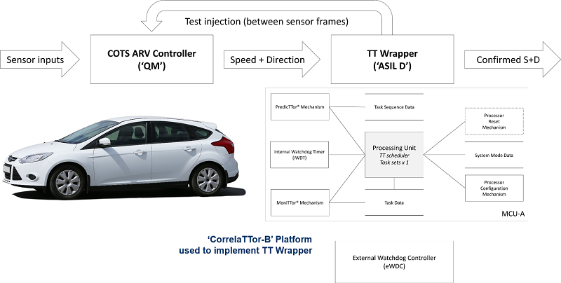
We receive several enquiries a year from organisations that have experience developing embedded systems using a general-purpose OS (typically Linux) and now need to demonstrate compliance with international safety standards (such as IEC 61508 for an industrial-control product or ISO 26262 for an automotive product). In these circumstances, we recommend that the organisation concerned considers the use of a TT Wrapper.
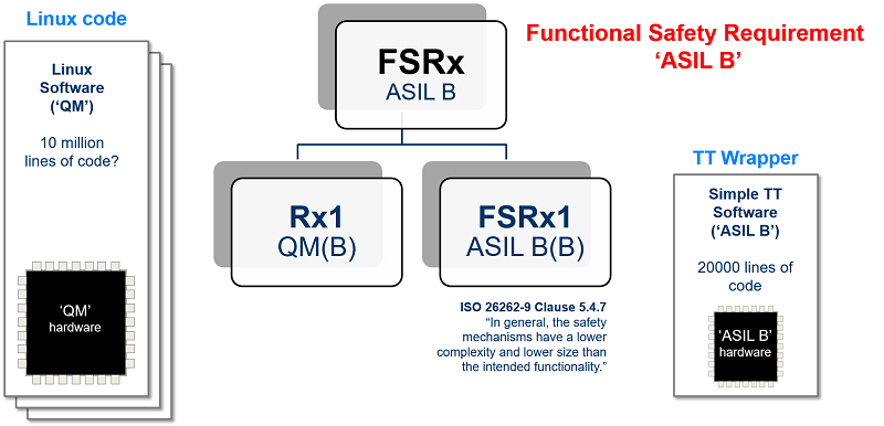
A TT Wrapper typically involves: [i] minimal changes to the Linux code or hardware; [ii] adding a low-cost MCU to the system that runs a TT software architecture and is used to monitor the behaviour of the Linux processor while the system is operating.
TT Wrappers are simple, cost-effective – and allow us (for example) to achieve ‘ASIL B Linux‘ for use in automotive designs.
Please note that TT Wrappers have many other applications (for example, in medical designs that involve ‘Software Of Unknown Provenance‘ – SOUP, and / or unqualified hardware).
We provide further examples of the use of TT Wrappers later in this guide (please scroll down).
![]()
![]()
Design examples: TT Systems
![]()
In the majority of cases, our customers use our ReliabiliTTy code frameworks to build a complete ‘TT System‘.
Here are some examples of TT Systems that are implemented using ReliabiliTTy code frameworks:
- A general-purpose automotive ECU (ISO 26262)
- A general-purpose industrial ECU (IEC 61508)
- An industrial monitoring system (IEC 61508)
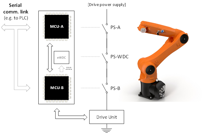
- A controller for an industrial robot (IEC 61508)
- ‘Steering-Column Lock Controller’ for a high-volume passenger car (ISO 26262)
- A controller for a domestic washing machine (IEC 60730 / IEC 60335)
- A space-based control system (ECSS-E-ST-40C, ECSS-Q-ST-80C)
![]()
![]()
![]()
Design examples: TT Wrappers
![]()
In some cases, our customers use our ReliabiliTTy code frameworks to build a ‘TT Wrapper‘: this is a monitoring unit that is used to improve confidence in the safe operation of a (pre-existing) complex component or system.
Here are some examples of TT Wrappers that are implemented using ReliabiliTTy code frameworks:
- ASIL B Linux (ISO 26262)
- Controller for an autonomous road vehicle (ISO 26262)
- Controller for a medical infusion pump that contains ‘SOUP’ (IEC 62304)
- Confirming that a machinery-operator is ‘in place’ (ISO 13849)
- Controller for a civilian aircraft system (DO-178C / DO-254)
PLEASE NOTE
We always recommend use of a TT System (rather than a TT Wrapper) when this is possible, because use of a System can provide higher levels of diagnostic coverage than a Wrapper, as well as increased confidence in system reliability. However, where (for example) designs need to employ a general-purpose operating system; or other ‘Software Of Unknown Provenance’ – SOUP; or ‘unqualified’ hardware components, use of a TT Wrapper may provide the basis for a practical and effective design solution. In addition, use of a Wrapper can provide an effective means of prototyping a safety-related system.
![]()
![]()
![]()
Learn more about our TT technology
 ‘The Engineering of Reliable Embedded Systems’ (ERES2) documents an industry-proven approach to the development of software for reliable, real-time embedded systems, based on the use of TT architectures.
The case studies in ERES2 describe the development of software for the following products: [i] an industrial alarm sounder unit (IEC 61508, SIL 2); [ii] a domestic washing machine (IEC 60730, Class B); [iii] a hospital radiotherapy machine (IEC 60601-1; IEC 62304, Class C); [iv] a steering-column lock for a passenger car (ISO 26262, ASIL D); and [v] an aircraft jet engine (DO-178C, Level A).
You’ll find further information on the ERES2 page.
Our ‘ERES2’ book is accompanied by a growing suite of public ‘Time-Triggered Reference Designs’ (TTRDs).
Used in conjunction with the book, these code examples are designed to illustrate ways in which TT software architectures can be used to support the development of a wide range of embedded systems for which safety is a key design consideration.
The latest suite of public TTRDs can be downloaded from our TTRD page.
![]()
![]()