Implementing a controller for an industrial robot (IEC 61508, SIL 3)
![]()
We receive many enquiries from organisations that need to develop embedded systems in compliance with international safety standard IEC 61508 (‘SIL 3’).
As an example of the type of design solution that we use in such products, we explore the development of a controller for an industrial robot on this page.
Our solution is based on a ‘Time Triggered‘ (TT) software architecture and two low-cost microcontrollers.
[This page was last updated 2021-01-04]
![]()
![]()
Key system and safety requirements
![]()
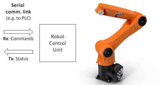
This design example considers a controller for an industrial robot.
![]()
![]()
The core system requirements in this example are superficially very simple:
- when the robot control unit (RCU) receives commands over the serial communication link, it shall ensure that the robot carries out the commands correctly;
- if the RCU cannot operate in compliance with the commands, it shall ensure that the robot enters a ‘fail safe’ state.
![]()
![]()
Relevant international safety standards
![]()
It is assumed that this system is to be developed in compliance with international standard IEC 61508.
IEC 61508 is concerned with functional safety, achieved by means of systems that are implemented primarily in electrical and/or electronic and/or programmable electronic technologies (for example, using microcontrollers – MCUs – and appropriate software).
TT software architectures provide a highly-effective way of meeting IEC 61508 requirements. For example:
- TT architectures are “Highly Recommended” for systems of Safety Integrity Level (SIL) 2 or above. [IEC 61508-3 (2010), Table A.2]
- Use of a TT architecture “Greatly reduces the effort required for testing and certifying the system” [IEC 61508-3 (2010), Table C.1]
In addition to these general considerations, ‘Hardware Fault Tolerance’ (HFT) is a key consideration in many IEC 61508 designs.
When HFT = 0, this means that there is only a single processing path available. If this path fails, it may be challenging to: [i] detect this failure; and [ii] ensure that the system can enter an appropriate ‘Fail-Safe State’.
When HFT = 1, this means that there is a second (independent) processing path available: if one processing path fails, the second processing path is intended to be able to both detect this failure and act appropriately (typically by forcing the system into an appropriate Fail-Safe State).
To achieve compliance with IEC 61508 at ‘SIL 3’ level, many designs employ an HFT of 1.
Use of TT architectures provides an excellent way of meeting ‘HFT = 1’ requirements.
![]()
![]()
Outline design
![]()
It is assumed that it has been determined that the RCU must be developed in compliance with IEC 61508 at ‘SIL 3’, using an architecture with HFT of 1.
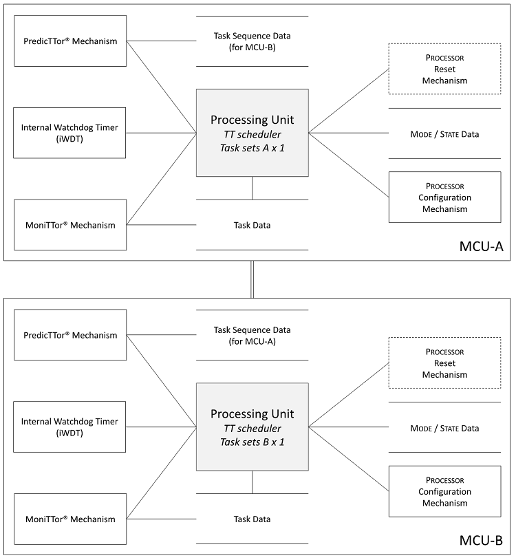
The design will be based on a ‘DuplicaTTor’ (TT) software platform, as illustrated below.
![]()
![]()
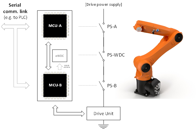
In this example it is assumed that:
- the RCU will perform control function (that is, it will cause the robot to move in accordance with directions received over the serial communications link);
- the RCU will monitor the operation of the robot to ensure that it moves as directed;
- the RCU will perform internal ‘self checks’, to ensure that it is operating correctly (the dual-MCU architecture will have a central role to play in such checks);
- if problems are detected in any of the control or monitoring operations, the RCU will ensure that at least one of the power switches (PS-A, PS-B, PW-eWDC) is opened, thereby disabling the drive unit and causing the robot to stop in what is assumed to be a fail-safe state.
![]()
![]()
![]()
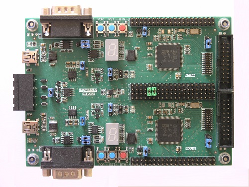
If required, this design could be prototyped on a DuplicaTTor Evaluation Board.
![]()
![]()
![]()
Related design examples
![]()
As outlined above, this design involves receipt of commands over a serial link.
Many control systems take this form (for example in medical systems, aerospace systems, automotive systems, …).
For example, a braking unit in a passenger car might employ a similar architecture.
![]()
![]()
Complete your cost-effective IEC 61508 design successfully using a SafeTTy Solutions™ package
![]()
The design example presented on this page is based on a SafeTTy Solutions™ Package (SSP-RTL4).
SafeTTy Solutions Packages are designed to help your development team produce a safety-related embedded system quickly and cost-effectively, in compliance with one or more international safety standards (such as IEC 61508).
SafeTTy Solutions Packages are based on TT designs and include carefully-selected combinations of our various products and services.
SafeTTy Solutions Packages include an appropriate ReliabiliTTy® Technology Licence.
Learn more about SafeTTy Solutions Packages …
![]()
![]()